Electron beam CNC system based on Raspberry Pi
This post is about an implementation of control system for fast elements of electron beam welding machine in BINP. My contribution in the development of this system was my master degree thesis. The core of this system is a single board computer Raspberry Pi. Special software was developed including libraries for low- and high-level technical process control written in C and Rust; and in-browser graphical user interface. The hardware was assembled and integrated inside machine infrastructure.
Electron beam machine
Electron beam technologies become increasingly applicable in different areas. Their principle is based on beam of electrons hitting the object in vacuum and locally heating it. This approach is used for precise cutting and welding, and also for 3D-printing. In our institute research of such technologies is carrying out and a couple of different electron beam machines have already been constructed. One of them is Small Experimental Electron Beam Machine which incorporates some interesting solutions like α-magnet and where experiments like 3D-printing with wolfram have been carried out.
Yu. I. Semenov et al. “3D printer mockup for manufacturing metal structures from refractory metals using electron beam additive technologies”, VI Conference of Lasers and Plasma Technologies (CLAPT–2015), March 24-27, 2015, Novosibirsk, Russia.
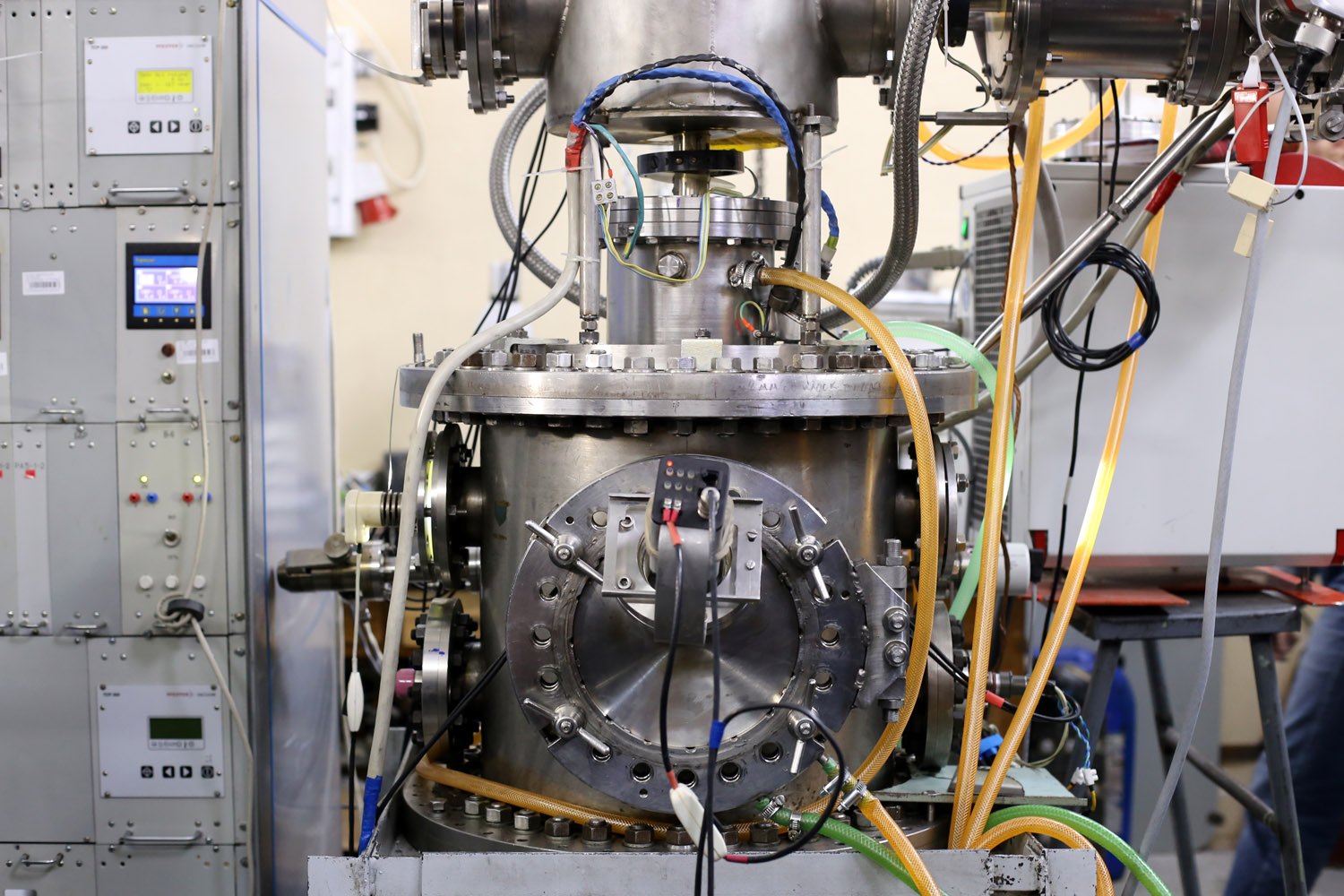
Small experimental electron beam welding machine at BINP.
Block scheme of the machine.
The machine contains so-called fast and slow components. Slow components like power supply and vacuum subsystem require the reaction time to be about one second and are successfully handled by general-purpose CX control system. But for some experiments it was necessary to handle specific components like beam deflectors or mechanical moving plates in more fast and precise manner with frequencies from 100 Hz to 2 kHz. The components that require such control are called fast components. Also the machine frequently undergoes reconstruction and improvements so its controls system should be easily updated too.
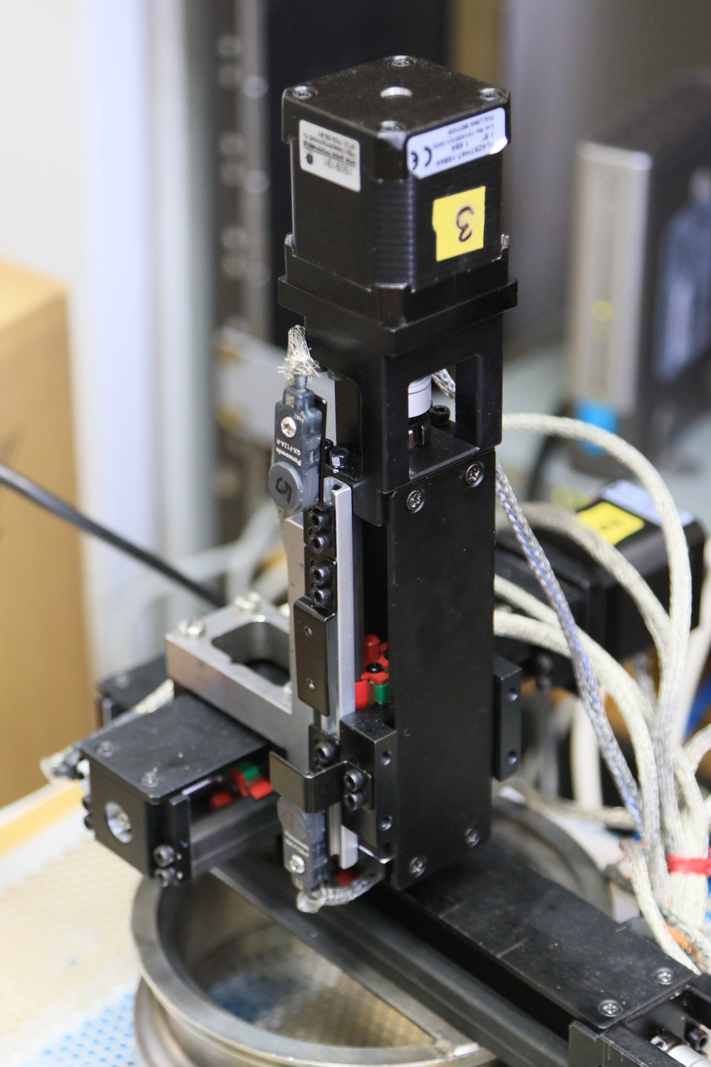
Mechanical moving plate.
Due to the experimental nature of the machine along with providing required performance and precision the control system of fast components should be flexible and easy to develop. We found that Raspberry Pi is the most suitable platform for such system implementation.
Raspberry Pi
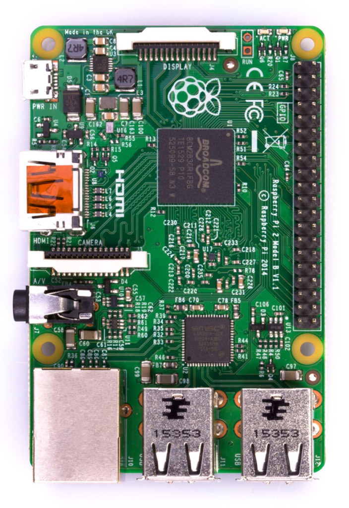
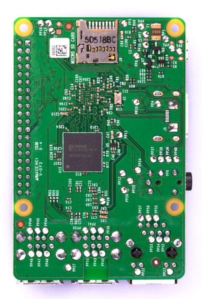
Rasperry Pi 2 Model B: front and back.
Raspberry Pi is a fully featured single board computer with GNU/Linux support. It is very suitable for quickly implementing a programming control for experimental hardware.
Raspberry Pi is a fully featured single board computer. There are several versions of this computer. We used versions 2 and 3.
- Version 2 is based on Broadcom BCM2836 system on chip (SoC) which contains 32-bit quad-core 900 MHz Cortex-A7.
- Version 3 is based on Broadcom BCM2837 SoC with 64-bit quad-core 1.2 GHz Cortex-A53.
There is also Graphics Processing Unit (GPU) on the chip - VideoCore IV 250 MHz and 400 MHz accordingly.
Along with CPU and GPU SoC also contains different peripherals devices:
- Ethernet
- 4 x USB
- WiFi and Bluetooth
- 40-pin GPIO
- HDMI
- 4 x SPI
- 2 x UART
- PWM,
- I2C
- PCM / I2S
Also there is a wide range of external adapters for Raspberry Pi to be put on top of GPIO.
Fast components control
There are two fast components required to be controlled with fast control system:
- 3 digital-to-analog converters (DAC) setting beam current and x- and y-deflection. The frequency of these DACs is 100 Hz. The communication with them occurs via CAN bus.
- Mechanical moving plate driven by 3 stepper motors controlled via low-level step-dir protocol with the frequency up to 2 kHz.
The first component is effectively handled by PICAN2 Duo Iso adapter mounted on top of the Raspberry Pi. This adapter is put onto GPIO pins and is controlled by Linux via standard driver that allows user space access via Socket-CAN interface. The latency of non-real-time Linux on Raspberry Pi is small enough to provide 100 Hz communication via CAN bus.
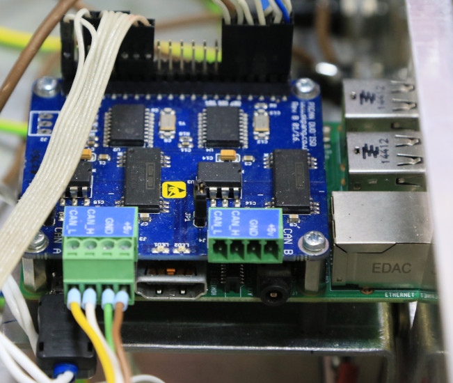
PiCAN2 Duo Iso adapter mounted on top of Raspberry Pi.
To operate the second component the latency of non-real-time Linux is too high. But we have found a relatively tricky way of generating such impulses via Raspberry Pi hardware peripherals - particularly DMA and PWM.
DMA on Raspberry Pi is the chain of control blocks where previous block points to the next. The block does very simple operation - it copies specified amount of bytes from specified source address into destination one. All peripherals including GPIO are mapped on the memory so DMA can also control the hardware. PWM controller is used to provide precise delay mechanism. Using this technique Raspberry Pi can generate impulses with the frequency up to 10 kHz and the timing precision is around 1 us that fully meets our requirements.
DMA blocks chaining in Raspberry Pi.
Control system
Software
The control system for fast components of Small Experimental Electron Beam Machine was called “RPi-CNC”. Its software part was designed to be modular and easily extendable. It has layered structure with increasing abstraction level and specified interface of each layer. The layers are listed below from bottom to top:
- Pigpio third-party library. It provides rich Raspberry Pi hardware management capabilities including tricky way of playing waveforms in real-time with frequency up to 10 kHz using DMA and PWM controllers.
- RPi-CNC library. This library consists of two parts: high-level and low-level parts.
- High-level part performs task managements, receives high-level tasks and translates them to low-level axis commands.
- Low-level part is written in C with optional modules written in Rust. It receives low-level commands for separate axes, synchronizes them and generates waveforms; also it handles signals from sensors. It interacts with the Raspberry Pi SoC hardware via pigpio library.
- Python3 binding wraps the C API of the library.
- Python3 web-server written in asynchronous manner using Aiohttp library. The server interacts with underlying Python3 binding of RPi-CNC library.
- Web-client with graphical user interface written in Javascript communicating with the server via Websocket.
Block scheme: low-level and high-level parts
Abstraction level stack.
Hardware
The hardware part includes CAN adapter for Raspberry Pi, stepper motor driver, custom proximity sensors adapter and power supplies for all this electronics and stepper motors. All the hardware was assembled into standard 19-inch rack mount chassis and integrated in experimental electron beam machine infrastructure.

The content of the hardware module.
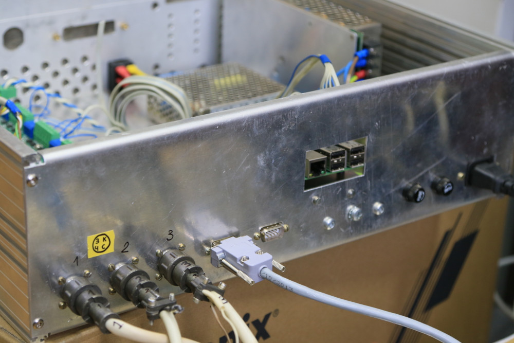
Connectivity of the hardware module.
Results
The control system was successfully applied to control electron beam technical process.
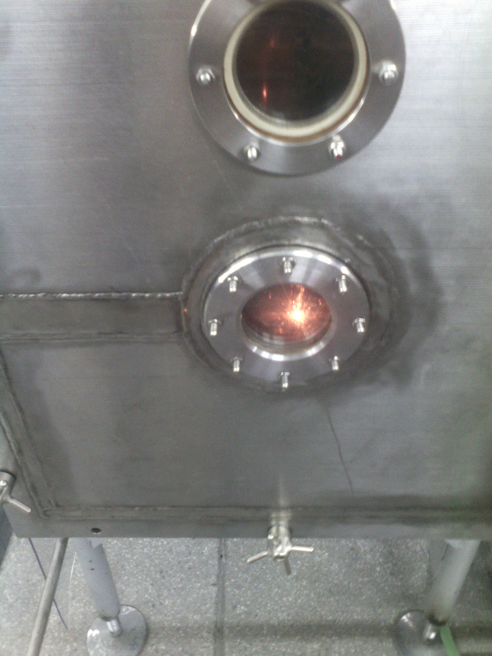
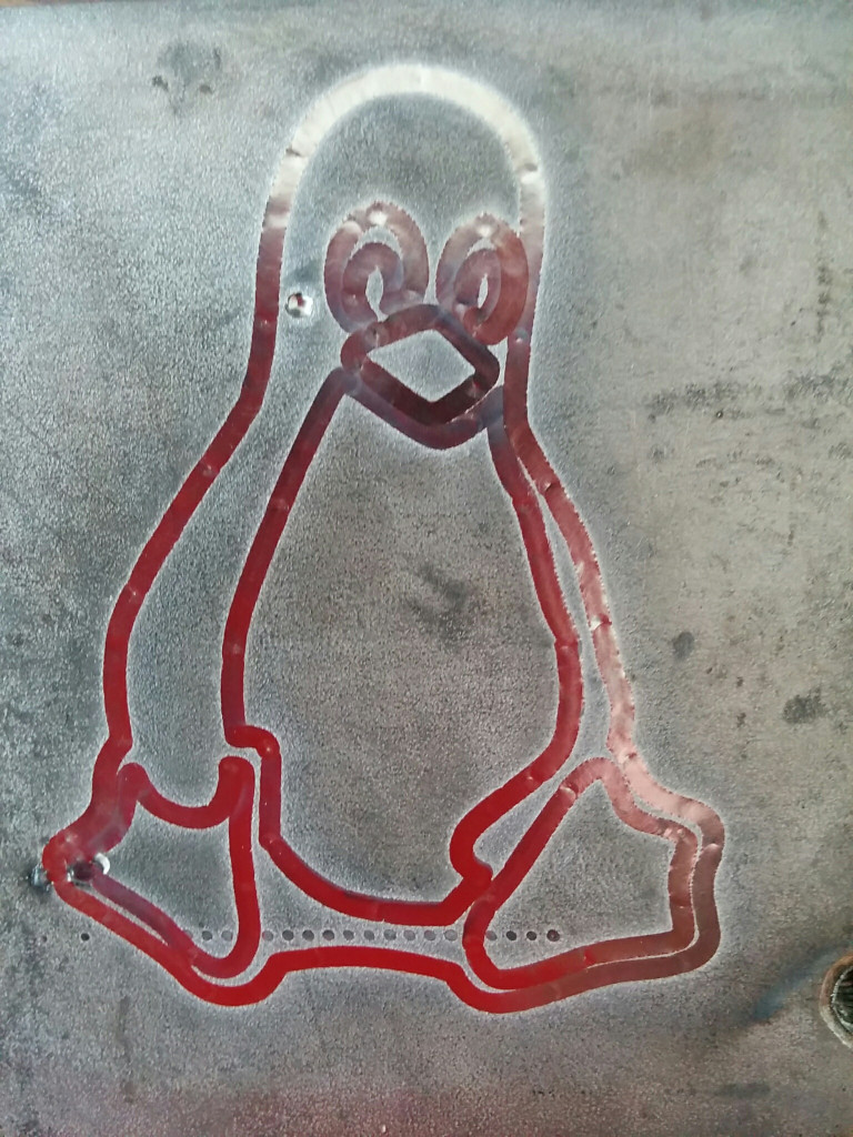
The process of drawing with electron beam on the steel plate, and picture got as result.
MIDI playback on stepper motors using RPi-CNC
The results was presented at ICALEPCS’19 conference.
Also, part of the developed software is used nowadays to perform automated diagnostics of particle accelerator magnets.